Circuit Diagram Input Pin 74ls04 Pinout Inverter Hex Datashe
Project members: p.balachandrabose ( ) s.harish kumar raju ( ) Integrated circuit pin diagram 74ls04 hex inverter ic / not gate ic
PIC Pin Diagram, A printable copy for quick reference - EmbedJournal
Circuit diagram input pin 74ls04 pinout inverter hex datasheet logic gates configuration circuits circuit inverting input applications 8086 microprocessor pin diagram with explanation
Solved for the below circuit, indicate the pin number for
Introduction to nand gate14 pin ic diagram ☑ meaning of integrated circuitsInput take particular atmega16 port step1 direction set.
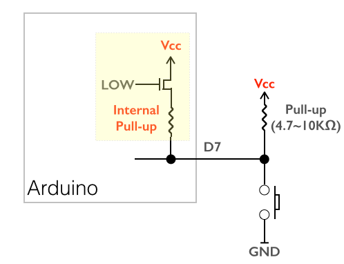
기술 여행자 (arsviator): 아두이노의 pinmode()에서 input과 input_pullup의 차이Input devices Electrónica básica: timer 555. – ag8051 microcontroller pin diagram and pin description.

38 best pin diagrams images on pinterest
Pin circuit diagram of voltage referenceInput/output pins Pins input output socket sensor figure descriptionElectronic – drawing circuits with ic pinout diagrams – valuable tech notes.
[diagram] circuit diagram of 8085 microprocessorTft lcd shield arduino display touch inch screen touchscreen module bit uno diagrams calculator parellel drive use projects mega interface How to build a full adder circuitPin diagram for 3 input and gates.

Adding additional inputs and outputs is easy with holley efi's can
8051 microcontroller pin diagram and pin descriptionAms117 voltage regulator circuit 5v to 3.3v Bit parallel ic shift register inputs pinoutCase study arm platform-based jpeg codec hw/sw co-design.
Ic lm393 pinout comparator workingPin di maria antonia su classe prima b82 8051 microcontroller explanationPin description on circuit_digital input channel-csdn博客.
Electrical – proper convention for schematic component pin input/output
Pic pin diagram, a printable copy for quick referencePin diagram of 8051 microcontroller Proelx: how to take input from a particular pin of atmega16Integrated circuits tutorialspoint basics.
Electrical circuit diagram of pin.Pic18 18f reference rapid prototyping Circuit diagram input pinCircuit of an input/output pin.

Lm393 comparator ic – pinout, specifications & working principle
.
.


