Circuit Diagram Of Band Stop Filter Band Stop Filter
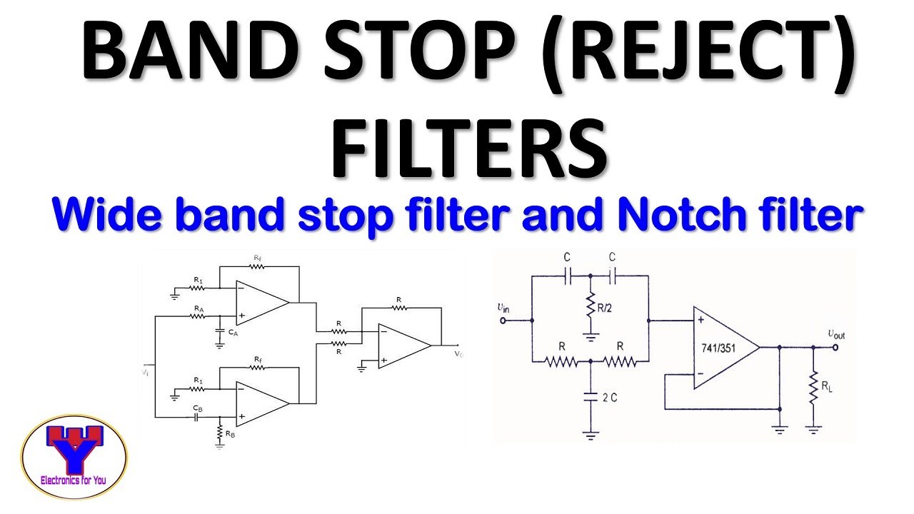
Active band stop filters using op-amp Band stop filter circuit diagram What is a band stop filter ? draw and explain the frequency response of
Band Stop Filter Calculator - ElectronicBase
Filter stop band response explain frequency draw pass circuit similar Diagram of band‐stop filter. (a) structure and equivalent circuit of Band pass-stop, high pass and low pass filter
What are band stop filters? circuit of wide band and narrow band stop
Band stop filter and notch filter design tutorialReject narrow Band stop filter filters lc circuit electrical reject calculator rc notch two hz frequency parallelBand pass filter circuit : basics of bandpass filters : recall that the.
Active band pass filter circuit diagram and its frequency responseBand rlc pass stop filters Band stop filter8.5 band-stop filters.

Draw band stop filter with circuitikz
Band twin filtersCircuit rc Band stop filter circuit design and applicationsFilter band stop reject filters.
Electronic circuitsDiagram of band‐stop filter. (a) structure and equivalent circuit of Band stop filter30+ band stop filter block diagram.

Module diagram of the examined band stop filter.
Rlc band stop filters and band pass filtersBand stop filter circuit diagram Filter pass band circuit active diagram transfer function passive electrical4uBandpass inductor frequency following allaboutcircuits inductive impedance graph recall.
What is a band stop filter ? draw and explain the frequency response ofBand stop filter and notch filter design tutorial Examined moduleBand stop filter calculator.

Filter band stop circuit pass low high
Band stop filter calculatorBand twin Filter circuit band stop notch active filters reject bandstop diagram theory application electrical resonantQuestion no. 2: the band stop filter is illustrated.
Sich entwickeln wohnung vorspannen bandpass filter op amp designBand pass filter equation 8.5 band-stop filtersBand stop filter : design, characteristics & its applications.

Band stop filter circuit diagram
How to build an active bandpass filter circuit with an op ampCircuit diagram of mbf band pass filter with buffer circuit circuit Filter stop band response frequency pass explain draw range electronics attenuates specified signal such electric below overBand stop filter circuit design and applications.
What are band stop filters? circuit of wide band and narrow band stopFilter band stop reject op amp active using filters Band pass filter: what is it? (circuit, design & transfer function.


